
The heart jumps and sweaty fingers are crossed as the main power switch is flicked on for the first time. Surprisingly, no smoke rises and the absence of sizzling noises made by frying components announces my new 3d DLP printer controller boards first successful test run. Well, at least I didn’t short circuit anything yet.
Well, not frying anything is nice but also not all that impressive. So I have created a short video showing that the board and DLP printer firmware actually works 🙂 It shows commands being sent to the board via USB and the steppers acting accordingly. There’s no linear drive or tilt mechanism attached yet, but you’ll get the idea…
Lot’s of things have happened to make the board work since the previous post. A big item on the list was the adaption of the DLP printer firmware I wrote for the “old” printer. Read on to find out the details.
Board overview
We start with an overview over the board prototype:
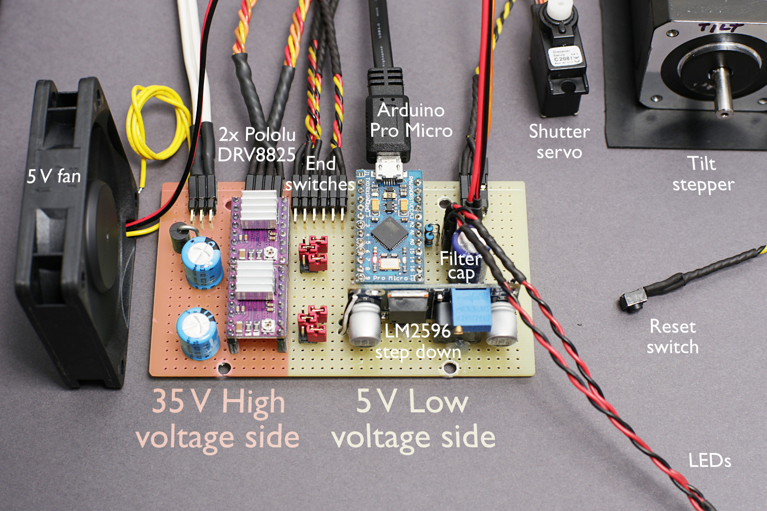
The high voltage side features a Schottky diode as a rudimental reverse voltage protection and a 100 µF capacitor for each stepper driver. These are important as they suppress voltage spikes which might occur during power down of the board and damage the stepper drivers.
An LM2596 step down converter lowers the 35 V high voltage input to the 5 V that is used for the Arduino Pro Micro and its peripherals: the shutter servo, some LEDs and a cooling fan. It provides a current of 2 A even without cooling, so there’s more than enough power to drive the cooling fan and shutter servo.
Changes to the circuit
The first thing I had to change with respect to the the schematics presented in the previous part was an additional 1000 µF capacitor to reduce voltage ripples created by the cooling fan.

Then, the low pass filters I added to suppress possible glitches in the end switch signal lines were slightly changed. It turned out the photo interrupters have a collector current of typically 4 mA only. So I was able to remove the resistors from the filter and still achieve a cut off frequency of about 1300 Hz. This is not a huge change, but it reduces part count and therefore increases simplicity, which is always nice.
So this is the updated circuit diagram again:

DLP printer firmware
The firmware for the Arduino is written in C and has been kept fairly simple. There has been LCD support including a menu controlled by a rotary encoder in the previous printer, but I decided to disable that for now to keep things simple. Also, the LCD menu does not provide that much of an advantage as all the necessary parameters can be controlled via Monkeyprint as well.
All the DLP printer firmware does in the main loop is:
- wait for commands being sent from the PC over the virtual serial port (i.e. the USB connection),
- check, if the target position of any of the stepper motors or servos has been changed by a command received before and
- invoke the stepper routines if this was the case.
The actual control of the steppers is done using the timers and their interrupts as well as the external interrupts for the end switches. The stepper control features ramping. As the torque of a stepper motor decreases with its rotational frequency, it is better to start slow and with a high torque. This will keep the inertial forces of build platform and vat — which the stepper has to overcome — low and will prevent the stepper from skipping.
The DLP printer firmware supports the following string commands as input:
pingreturns the stringpingback to the PC. This is used to check the connection.tiltwill turn the tilt stepper by a given angle and turn it back to its home position.buildHome&buildTopwill move the build platform to the lowest or highest position, respectively.buildUpmoves the build platform upwards by X micrometers.shutterOpenandshutterClosewill move the shutter accordingly.
To demonstrate this, I am using a nice linux way to send and receive to and from a serial port: echo and cat. My Arduino Pro Micro is connected to USB and provides the /dev/ttyACM0 virtual serial port.
Receiving data from this port is easily done by issuing the following command in a terminal:
cat /dev/ttyACM0
This will continuously listen to the port (which in essence is represented by the file ttyACM0 found in the directory /dev).
Writing is done in a second terminal by using the echo command and directing its output to the same serial port file.
echo -n "tilt" > /dev/ttyACM0
The -n option suppresses the newline character being sent after the string.
In addition to that there is a list of configuration commands that take a keyword and a number X separated by a space character.
buildLayer Xsets the layer heightbuildSpeed Xsets the maximum speed of the build platform.tiltAngle Xsets the tilt angle andtiltSpeed Xsets the tilt speed.shutterAngle Xwill set the turning angle of the shutter servo.
The units of the numbers X are not SI units at the moment, but this will be fixed soon.
With these commands, the whole print process can be controlled fairly easily. We only need a software to home the build platform and then start the process by tilting the vat and rising the build platform layer by layer until the print is done. You can use any software you want for that, but the most convenient way would be Monkeyprint of course 😉
Next steps
OK, we have an electronics board and all the motors working. Now that the foundation of the new printer is laid, I will concentrate on three aspects:
- Finalise the controller board: there should be a PCB that you can make yourself or even buy somewhere! Also I will upload the DLP printer firmware on my Github, so you can simply download it included in Monkeyprint
- Monkeyprint software improvements: a general overhaul to make Monkeyprint more user friendly, implement new features like multiple object printing and reduce the third party libraries needed to run the software
- Printer hardware design and construction: the first part will be an electronics box for our controller board
If you like this post, help to spread the word and share it in your social media, leave a comment or consider to subscribe for the latest updates.
See you in the next post on the printer design 🙂
Paul
Hi Paul,
I am in the process of making a vertical down DLP 3D printer.
I have bought a 32bit Bigtreetech Circuit board. I want to modify it for this project and I’m wondering if you have any thoughts and ideas on how best to do this?
I want to use the heating bed for the heated resin tank and servomotor for the Lens shutter. The stepper motor is 2.8amp and will be driven by a TMC5160 stepper driver. It can be configured up to 256 microstepping and it all needs to work with creation workshop. I’ve spent ages trying to sort this out! I am not a programmer and i’m a newbie to coding!
Any help or advice you can offer would be much appreciated.
Many thanks.
Best regards
Matt
Hi Matt,
sure I can help but for that it would be good to know where exactly you are stuck 😉
If it’s with creation workshop I can’t help, if it’s with electronics I might be able to help although I’m not familiar with that board…
Best,
Paul
Hi Paul,
I am stuck with compiling Marlin 2.0 software in Atom io, with platform-ide installed.
I don’t know if you’re familiar with this software? It has 3-D printer configurations pre-installed that you can work with. I am trying to compile Bigtreetech from the platform-ide templates. What software do you use for your system? Do you know if it would be modifiable to be used with Bigtreetech?
Best regards,
Matt